Mar 2016
Brake Gear and Hart Gondolas
March 17, 2016
Brakes and Hart Gondolas
When I did the initial research for the Hart convertible gondolas, I was able to find great drawings of the car bodies, but little on the brake equipment. The California State Railroad Museum has a few drawings of the W-50-3 gondola, all with beautiful detail. There was no information either about the routing of the brake rodding, or details about pipelines and fittings.
The current Hart gondola kit instructions suggest a possible “simplified” brake rigging for modelers who want to get this detail perfect. On my own cars, I added this “simplified” brake gear on about half the cars, but did minimal detail on the others. My layout, after all, is an operating layout, and having cars that work smoothly and don’t hang up matters more to me than having contest models.
I know many others who want their cars to be perfect, right down to the brake gear. Luckily, I found another source for information about these cars. The SP’s W-50-3 happens to be a “Common Standard” design, shared between the different Harriman-owned railroads through the ‘teens, so the Union Pacific or Pacific Electric also had the cars.
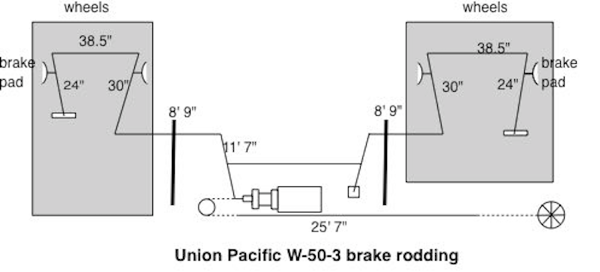
California State Railroad Museum’s collection of Union Pacific blueprints gave the missing link. UP’s “Air Brake Folio (dated March 5, 1919, book 430, drawing 5242-30) had schematic drawings of many cars. That drawing of the W-50-3 brake gear highlights exactly how the rodding was placed.

There’s some key details worth noting if you want to install prototypical brake rodding:
1) Note that the brake cylinder end attaches to a chain that goes around a pulley before stretching to the brake wheel. On all the Southern Pacific cars I’ve seen, no such pulley exists; the brake wheel pulls a chain directly connected to the brake cylinder.
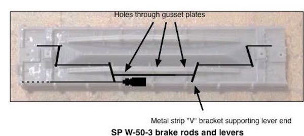
2) The 11’ 7” rod behind the brake cylinder is interesting; on the real cars, it had to pass through holes in two gussets attaching the Hart truss to the car floor.
3) The pivot point behind the brake cylinder does appear on the real cars as a pair of steel straps in a V design holding the pivot end of the brake rod. This pivot support isn’t easily seen in all photos, but the builder’s photo of Pacific Electric 6000 in Tony Thompson’s “Southern Pacific Freight Cars” book shows the support faintly.
If you'd like to put full brake gear on your SP W-50-3 Hart convertible gondola, here's how the rodding would fit on the car body.
The UP’s “Air Brake Folio (dated March 5, 1919, book 430, drawing 5242-30) is available at the California State Railroad Museum; the image of the blueprint is on microfilm.
When I did the initial research for the Hart convertible gondolas, I was able to find great drawings of the car bodies, but little on the brake equipment. The California State Railroad Museum has a few drawings of the W-50-3 gondola, all with beautiful detail. There was no information either about the routing of the brake rodding, or details about pipelines and fittings.
The current Hart gondola kit instructions suggest a possible “simplified” brake rigging for modelers who want to get this detail perfect. On my own cars, I added this “simplified” brake gear on about half the cars, but did minimal detail on the others. My layout, after all, is an operating layout, and having cars that work smoothly and don’t hang up matters more to me than having contest models.
I know many others who want their cars to be perfect, right down to the brake gear. Luckily, I found another source for information about these cars. The SP’s W-50-3 happens to be a “Common Standard” design, shared between the different Harriman-owned railroads through the ‘teens, so the Union Pacific or Pacific Electric also had the cars.
California State Railroad Museum’s collection of Union Pacific blueprints gave the missing link. UP’s “Air Brake Folio (dated March 5, 1919, book 430, drawing 5242-30) had schematic drawings of many cars. That drawing of the W-50-3 brake gear highlights exactly how the rodding was placed.

There’s some key details worth noting if you want to install prototypical brake rodding:
1) Note that the brake cylinder end attaches to a chain that goes around a pulley before stretching to the brake wheel. On all the Southern Pacific cars I’ve seen, no such pulley exists; the brake wheel pulls a chain directly connected to the brake cylinder.
2) The 11’ 7” rod behind the brake cylinder is interesting; on the real cars, it had to pass through holes in two gussets attaching the Hart truss to the car floor.
3) The pivot point behind the brake cylinder does appear on the real cars as a pair of steel straps in a V design holding the pivot end of the brake rod. This pivot support isn’t easily seen in all photos, but the builder’s photo of Pacific Electric 6000 in Tony Thompson’s “Southern Pacific Freight Cars” book shows the support faintly.
If you'd like to put full brake gear on your SP W-50-3 Hart convertible gondola, here's how the rodding would fit on the car body.

The UP’s “Air Brake Folio (dated March 5, 1919, book 430, drawing 5242-30) is available at the California State Railroad Museum; the image of the blueprint is on microfilm.